We lay wiring in the apartment. Pue and snip requirements for the installation of electrical wiring in the apartment. Wall work
Is it possible, in principle, for an ordinary unprepared person to carry out electrical wiring of an apartment
do-it-yourself turnkey?
I answer. If you are not a pathological lazy person, then definitely yes.
This article presents one of the parts of a practical guide to implementation, do-it-yourself wiring in an apartment with step-by-step instructions, with detailed comments and explanations by the author. I want to draw your attention to the fact that similar video and text material is published on the network as a paid one, on this resource it is presented from beginning to end completely free of charge for all site visitors.
In this manual, we will analyze in as much detail as possible the issue of performing stationary electrical wiring in an apartment exclusively with our own hands, and the whole process will be considered from the very beginning to the end.
Briefly about what includes step-by-step instructions for wiring in an apartment with your own hands:
- Stage 1. Preparation and implementation of the wiring diagram of the apartment. Selection, brands and calculation of the cross-section of wires, room illumination, as well as electrical circuit protection devices.
- Stage 2. Installation of electrical wiring. Laying of wires, connection of wire cores in junction boxes. Installation and connection of a power apartment shield. Checking the completed electrical wiring.
- Stage 3. Installation of socket boxes (installation boxes).
- Stage 4. Installation of sockets and lamps. Connecting household appliances that do not have stationary sockets.
Who will benefit from this guide?
First of all, those who have decided or plan to perform a complete or partial installation, replacement of the electrical wiring of an apartment or room on their own. And also for those who want to perform high-quality electrical wiring using the services of electrical installation of private firms or organizations.
Based on the fact that this topic is very large and simply physically cannot be compressed into one article, the material is divided into several small, but as detailed as possible parts.
What is an apartment wiring diagram and why is it needed?
Let's start from the very beginning.
First of all, in order to perform electrical wiring, we need an electrical circuit of the room.
The wiring diagram is a plan of the room, which schematically depicts the following elements:
- Sockets.
- Switches.
- Lighting lamps.
- distribution boxes.
- Power shield.
- Places of electrical outlets for the subsequent connection of various equipment to them (for example, air conditioners, hobs and ovens, forced ventilation).
- The route of laying the wires of the power and lighting parts.
An example circuit is shown in the figure below.

Why do you need a room wiring diagram?
The explanation should begin with the fact that the wiring diagram is the foundation of a well-executed repair. And that's why:
- It is with the wiring that any overhaul begins.
- The subsequent stages of repair will close access to almost all changes in the electrical wiring of the room.
- The final indicator of the level of comfort of the room (if we talk about high-quality repairs) will again be an electrician - this is sufficient illumination of the room, conveniently located and in the right places sockets and switches
Important! A correctly drawn up diagram is a guide to the competent execution of all electrical wiring in any room.
I will describe one of the many advantages of wiring according to the scheme, which will clearly show the end users the importance of this stage.
We are all familiar with the following.

That's right, these are various kinds of extension cords, network adapters and carrying. If we consider the finished electrician of the apartment from the point of view of comfort, then the absence or minimal use of the mobile electricity transfer device presented above will be one of the criteria for a well-thought-out electrical wiring. After all, if, as a result of the completed repair, you have half of the sockets in places where large-sized furniture (wardrobes, beds, sofas) will stand, then with a hundred percent probability those very ill-fated extension cords and carriers will be lying around the entire floor of the apartment. The question arises, why then do new wiring at all?
An example of wiring without a diagram.
Before us is a one-room apartment, which consists of 4 rooms:


- Kitchen.

- Bathroom, toilet (joint execution).
- Hallway.

Using the example of a large living room, without relying on how it will be stranded, let's try to arrange sockets over the area of \u200b\u200bthis room.
Let me remind you that our room is a hall.
It is most logical to distribute sockets at different ends of the room. For example, yes.

Based on my own experience as an electrician, I note the following, in 90% of cases, the distribution of sockets occurs, so to speak, “from the bulldozer”, and they are distributed either in a hurry by the owner, who is driven by hardworking plasterers and plumbers, or they are distributed at their discretion by an electrician. What this negligent attitude leads to, we will see in the following figures.
The repair is completed, furniture and household appliances are arranged.


Where will the outlets be?

Of the 4 sockets distributed throughout the room, 2 will be blocked by furniture and will never be used.
What are we losing? Let's figure it out:
- Forces and time for laying wires, installing 2 socket boxes (mounting cups) and installing 2 sockets.
- Money to buy 2 outlets, extra meters of wire, 2 sockets (mounting cups).
And given that the installation will be carried out by hired electricians, then here it is worth adding the cost of laying the wire, installing socket boxes (mounting cups) and sockets.
I think that in the process of repairing the money spent for nothing can be found in a more necessary and useful application.
With a fairly simple example, we saw how important a wiring diagram can be. I note that we have dismantled only one room of the apartment presented in the example. Imagine what happens if you make mindless electrics everywhere.
Now that we have an understanding of the importance of compiling and wiring an apartment, we can move on to part 2 of the step-by-step instructions for wiring an apartment with our own hands.
It is worth saying that the electrical wiring of any room is strictly individual. Therefore, we will consider the main points of installing electrical wiring in an apartment. So, first you need to enter the input cable into the switchboard. The electrical panel contains a device for recording electricity - an electric meter and protection devices - circuit breakers, ouzo, differential. automatic machines, etc. The electrical switchboard can be located in a niche (internal installation) or on a wall (consignment note). The most optimal placement of the electrical panel immediately near the entrance of the apartment hallway.
Optimal placement of the electrical panel immediately at the entrance of the electrical panel - wiring for the apartment
Video. The secrets of assembling the electrical panel and wiring in the apartment
You need to lay a copper wire with a cross section of at least 6 mm 2. The installation of the electrical switchboard is placed at a level of 1.5 m from the finished floor. This provides access to various devices for their inspection, taking meter readings and preventive maintenance. The operation of protection devices is optimized depending on the power consumption.
Hidden and open wiring in the apartment

Now most apartments use electrical wiring hidden under plaster. In drywall partitions, the wire is pulled in a special protective sleeve. External wiring in the cable channel does not look aesthetically pleasing; this method of laying the conductor is more suitable for office space. In the apartment, the cable channel is laid as an exception.
Wiring in the cable channel

To install hidden wiring in the wall, a recess of up to 2 cm is made. Such an action is carried out only when the wall is completely marked. Along with this, recesses for sockets and switches are made vertically above these installations, but not diagonally, in an attempt to shorten the path of the conductor. The conductor for consumers must be laid straight - perpendicular. Preliminary fastening of the wire is carried out using dowels - clamps, and after that it is plastered. An excellent option when the wire is pulled in a protective sleeve, but this leads to an increase in the cost of electrical wiring. The protective sleeve allows you to stretch the wires without disturbing the plaster in the future, if you need to replace or repair the wiring. Along with this, the use of a protective sleeve or pipe creates protection for electrical wiring.
Electrical wiring in a protective sleeve

Basically, for electrical wiring in the apartment, a copper wire in PVC insulation is used. The conductor must be single-core, it oxidizes much less along with stranded copper wire.
The installation of special boxes for sockets and switches should be flush in the wall and should not stick out, otherwise they will cause a lot of trouble when installing electrical installations. The fastening of the socket boxes is carried out using a mixture of alabaster or rotband.
Power lines should be laid, starting from the shield, which is installed at the entrance to the apartment separately for sockets and lighting. After that, electricity is distributed throughout the room through junction boxes. In the junction boxes there is a small supply of wire up to 10 cm for subsequent disconnection. It should be noted that this type of wiring has been used for a long time, and in most old residential premises it has been preserved to this day.
Junction box for disconnecting wires

Automatic protection for electrical wiring in the apartment
Modern analogues of apartments have several groups of power lines. In such a scheme, the installation of an RCD is mandatory, which will protect the family from electric shock. In modern wiring, more protection devices and wires are used, so its cost increases significantly. Such expenses are justified by increasing the level of reliability of the power supply network. Thanks to this wiring, independent lines are formed, which later lead to easy troubleshooting.

Wiring for electrical installations

Any of the rooms must be equipped with a standard type of lighting, which can be supplemented by local lighting in the form of a floor lamp, wall lamp, table lamp. Most experts believe that it is enough to use 1 outlet per 6 square meters. meters of room area. For computers and TVs, you can provide a block of outlets. In the kitchen area, homeowners have many different household appliances, which include a microwave oven, dishwasher, juicer, etc. therefore, it is prudent to provide a sufficient number of outlets and conductors.

The location of the switches is often determined not far from the door at a distance of 10 cm from the doorway and 90 cm from the level of the finished floor. The main thing is that when the door is opened, access to the switch is not blocked. The level of sockets should reach 30 cm from the floor level. Most experts recommend purchasing ceramic-based switches and sockets with copper contacts.
Immediately before the installation of sockets in the premises, it is necessary to determine their location, as well as the relevance of their installation, the cable laying route, the volume of wires, and the location of the junction boxes.

For optimal connection of sockets, a copper cable of the VVGng brand is used. This element is necessary for internal laying, as it is covered with special insulation that prevents combustion. The size of the cross-section of the wires in the cable is directly related to the results of the power of electrical appliances. Basically, this figure reaches 2.5 mm. It contains several cores in the form of a phase, zero and earth. In old building structures, where there is no grounding in the electrical distribution panels, a two-core cable (phase, zero) is used.
The geometry of the wiring in the apartment

It is always correct to lay electrical wiring in horizontal-vertical lines, regardless of whether it is in a cable duct or under plaster. But still, it is often possible to find wiring laid by the shortest path, arbitrarily. Such a trick is used for several reasons: due to the saving of electrical wiring, ignorance of the rules of electrical installation, negligence of the electrician, in order to save time and effort. Why is it so important to observe the geometry of the electrical wiring?
Scheme of incorrect wiring

They made repairs, rearranged the furniture in the house, decided to hang a new picture in the resulting space, outlined it, take a puncher, drill and get exactly to the place where the sparks fly out. Such a scenario is not contrived, this is a common occurrence, I myself once landed in such a place, although there was a choice to drill a centimeter to the left or a centimeter to the right. I had to correct the mistake and repair the damage.
So, improperly laid electrical wiring increases the risk of de-energizing part of the line one day. After a good repair, it is not always so easy to fix a broken wire.
The wiring rule for laying electrical wiring is very simple: where a socket or switch is installed, the wiring must go down strictly vertically to electrical installations. If you need to hang a picture in the future, the risk of damaging the electrical wiring is reduced to zero.
Wiring must be laid strictly vertically or horizontally

Such elements are laid along corrugated plastic pipes in order to protect against insulation damage during finishing. The laying route should contain only horizontal and vertical zone types. It is not recommended to use diagonal zones. In addition, cable turns and intersections with other cables must be made at right angles. The distance from the ceiling should reach a maximum of 15 centimeters.
Correct wiring diagram.

Vertically laid wires must be at least 100 mm away from door and window openings. Near the heating pipes, the laying should be carried out at a distance of at least 150-200 mm, at a perpendicular intersection, the electrical wiring should be protected with asbestos gaskets. Parallel laying near pipelines with combustible substances (gas) is carried out at a distance of at least 400 mm. It is also necessary to follow the sharp corners of concrete, metal parts and shrinkage of the building.
At what height from the base of the ceiling is the electrical wiring laid? Minimum 150 mm, (depending on ceiling height), i.e. the principle is this: if you plan to install a suspended or stretch ceiling, the wire must remain in the accessible area. If the new ceiling is lowered by 300 mm from the main ceiling in an apartment with high ceilings, the electrical wiring should be laid at a distance of 400 mm. You need to take into account such a rule even if you are not currently planning suspended ceilings.
How to lay electrical wiring in a panel house?
Most often, in panel houses, electrical wiring to sockets is laid in special technical channels not vertically, but with a slope, on average, under 45 0.
Wiring diagram in a panel house

If you need to move or lower the switches and sockets to another convenient place, it is enough to make a small recess in the panel to drown the wiring. If the previous place of the outlet at a height of 1 meter does not suit you, and you decide to move it lower, at a distance of 300 mm from the floor and slightly to the side, the principle remains the same - we lay it straight perpendicular.
Electrical wiring in a panel house

How to lay electrical wiring in the floor and ceiling
If a stretch or suspended ceiling is planned, the electrical wiring can be laid on the ceiling arbitrarily, in the shortest possible way, for example, the NYM cable does not require additional protection, as it has triple insulation and does not support combustion. The cable VVG, VVGng, is laid in PVC corrugation. The cable is fastened to the ceiling on the dowel clamps or special holders (clips) fixed in the corrugation.
Electrical wiring in the floor

Under a wooden floor, they are also laid arbitrarily, in metal-corrugated or metal pipes. If in a screed, then the wire is laid in PVC corrugation, arbitrarily.
There should be no junction boxes on the ceiling and in the floor, i.e. connection of wires and wiring of conductors should not be. All laid wires must have continuity, from the switchboard to the consumer or from the junction box installed in the wall to the consumer. If the box were in an inaccessible place, then in the event of a failure in the contact connections, it is impossible to eliminate the malfunction. Junction boxes must remain accessible for repair or maintenance work.
Corrugated ceiling wiring

Electrical safety during the installation of electrical wiring

It is also worth mentioning the safety rules when connecting sockets and laying cables. Most experts do not recommend laying the cable when it is energized. This is due to the fact that a person can get an electric burn or even die. Therefore, before working with the cable, it is necessary to check whether it is de-energized. This will require the use of a special device. To increase the level of reliability, the cable must be disconnected from the electrical panel. You need to know that all electrical work in the apartment is carried out after the mains is de-energized. And the wires are brought to power at the last stage. Such actions can be carried out independently, but for this you must adhere to the established rules. However, this work should still be entrusted to trained people.

Video. How to lay electrical wiring in the apartment?
The comfort of life of a modern person directly depends on the availability of a reliable source of electrical energy. Almost everything is tied to it - lighting, cooking and food storage, space heating and water heating, air conditioning and ventilation, means of communication and access to information, dozens of other devices and devices, without which it is already difficult to imagine our existence.
Electricity suppliers in our time work stably, without serious and prolonged failures, and if the consumer pays for services on time, then he can count on full access to the available "benefits of civilization". But only energy supply companies guarantee the supply of voltage to the “watershed” - to the consumed energy. And then the area of responsibility of the landlord begins, and it is in his right to arrange all points of lighting and connection to the power grid in the optimal quantity, from his point of view, and in a convenient place for use. But how to approach this issue? Will the wiring be installed in the apartment with your own hands, or is it more expedient to use the services of electricians?

It is impossible to answer this question unambiguously. Much depends on preparedness, "savvy" landlord in the field of physics, electrical engineering. An important factor is the ability for long-term planning, since replacement work postings are implied for many years to come. And, in the end, the owner of the apartment must have a good set of skills in the field of general construction work - it will also not do without it.
 In laying wiring - a considerable component of general construction work
 The purpose of this publication is to give the owner of the apartment an idea of the scale of the measures for laying the home electrical network, about basic principles its planning, the correct distribution of loads, installation techniques and electrical fittings products, about other important nuances. It will be possible to understand whether it is worth taking on such a volume of work on your own, or still invite qualified craftsmen. From the point of view of professionals, without practice and without electrical safety clearance, it is better not to do such work on your own, since there are a lot of nuances that simply cannot be described on the scale of one article - their knowledge comes with many years of experience. However, know basic principles wiring in an apartment will be useful to any owner - it will become possible to control the work of the masters (alas, there are rogues among them), and for the safe operation of housing, such an understanding of the issue will never be superfluous.
When is it time to start laying new wiring in the apartment?
Anyone who received a new apartment in houses that were built and rented out according to the old principle - "turnkey" (although, as a rule, with not very high quality), knows how, often inconveniently, thoughtlessly, connection points to the power grid were placed there . Yes, everything corresponded to the old GOSTs, but the trouble is that these standards were written when the saturation of human life with a variety of electrical appliances differed significantly from current conditions.
As you acquire new appliances, you have to stretch extension cords around the apartment or even lay new lines, since some electrical installations clearly do not have enough rated power of old wires. stretching by by Lam cables are both a feeling of certain discomfort, and a clear minus for the interior design of the room.

Moreover, with insufficient connection points, many tenants who are poorly versed in electrical engineering make sometimes unimaginable connections using tees, even using them in several cascades. Alas, this is a direct road to the occurrence of a fire hazard in the apartment.
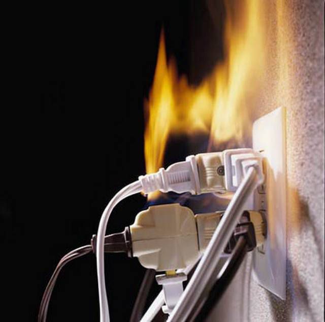 But this is already a direct path to big trouble.
 And so, when sooner or later it's time to make a major overhaul in your apartment, the most reasonable step is to completely, from the entry point to the last outlet, replace both the wiring and the entire electrical fittings part by planning the installation of power connection points in the most convenient, rational and safe way.
There is another very important reason to ever completely change the cable part. The fact is that during the construction of high-rise buildings in the old days, for reasons of economy, internal wiring was in most cases made of aluminum wires. Aluminum seems to have good electrical conductivity characteristics, but now it is practically not used for these purposes, since its disadvantages far outweigh its advantages.
- First, the metal itself is very soft. It is easily deformed, pressed through when using contact screws, terminal washers, etc. - it is unlikely that it will be possible to make contact twice in one place - the wire will simply break in a thinned place. That is, repair work with aluminum wiring is extremely difficult. Soldering it is very difficult, and in the conditions of installing home wiring it will be extremely irrational to use this technology.
- However, aluminum is only ductile when it is, let's say, "fresh". This metal has an amazing property - the electrochemical processes that occur in it during the passage of current radically change the properties of the substance over time. After 15 ÷ 20 years of operation (and for wiring - this is a very short time) aluminum conductors become brittle. Sudden, almost causeless, are not excluded, which can be very difficult to find, and even more difficult to eliminate, since the wire can break even with careful attempts to make a new twist or bend it for a terminal connection.
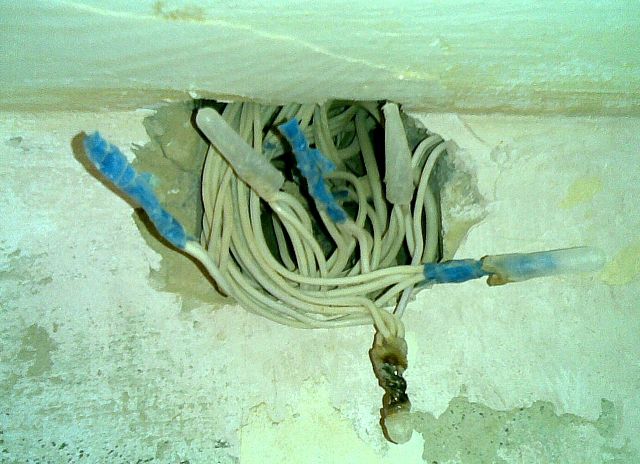
- Another striking property: it would seem that the metal is very resistant to corrosion, but it was not there! If even a small amount of water gets on the conductor, then under the action of electricity, electrocorrosion processes are inevitable. And, they may be invisible externally - in appearance, the whole conductor inside can be “corroded” so much that even a small one causes heating, sparking or failure. Sometimes any touch to such a wire leads to its breaking off.
 Compare with the picture above - is there a difference?
 In other words, if you are serious about electrical issues, then you should not hesitate to replace all the old aluminum wiring with on the reliable copper. Its electrical parameters are even higher, plasticity is good (but not excessive), and does not change either from time to time or from operation under heavy loads. The cost of copper wires is, of course, significantly higher, but the wiring in the apartment is done, as already mentioned, for decades to come, and saving on such issues is simply unreasonable. Along with the replacement, you can simultaneously solve all issues with the optimization of the placement of all elements of the home electrical network.
If the owner has purchased a new apartment, in a house that was commissioned on a do-it-yourself basis, then there is nothing to think about - you need to carefully plan the entire apartment electrical network, taking into account your vision of the location of electrical appliances and furniture in the rooms, and literally do the wiring in the first place - even before pouring floors, finishing walls and ceilings. Below in the text it will become clear why this is so.
A few more arguments in favor of not upgrading or repairing, but overhauling the old wiring.
1. In the old days, ground loops in residential buildings were not considered mandatory, and all intra-house networks were laid according to the TN-C system, when the working zero and ground were connected to a single wire (PEN) even at the electrical substation. The only advantage of this approach is ease of installation and minimal material consumption, since all sockets in the apartment were entangled with only two wires - zero and phase.
 TN-C system - "the day before yesterday" of electrical engineering
 During a reboot or a breakdown on the metal case of electrical appliances, a life-threatening voltage is very likely to appear. Moreover, this type of contact connection does not allow correct operation of residual current devices (RCDs), some modern switching power supplies. Today, such a system is not used, in some places it is even prohibited by law, and it must be changed to one of the more advanced systems: TN-S or TN-C-S.
TN-S is more often used in private houses in which their own is organized. Although, in apartment buildings, grounding buses can be organized, connected by welding and passing from the external ground loop through all floors.

But still, the TN-С-S system is used more often in multi-storey residential buildings, in which deaf-earthed the neutral is divided into two conductors - a working zero and a ground loop, directly in the access switchboard.

In any of the last two cases, three contacts are already used for wiring - phase, zero and ground. You can immediately mention the color marking of these wires - one must comply with current standards.

Please note that the color of the phase wire may vary. But here, zero and grounding - have a mandatory color, so that it cannot be confused during electrical work.

By the way, several phase conductors can be enclosed in one cable. They will differ in color from each other, but at the same time, two conductors will still stand out with their obligatory color - “working zero” and “ground”.
A lot of modern electrical appliances are equipped with a three-prong plug. So, an important clarification needs to be made. When installing new sockets, the owners, of course, also try to install three-pin ones. However, if wiring has not yet been organized in your apartment according to the TN-S or TN-C-S schemes, then in no case should jumpers be made between the zero contact and the ground contact directly on the outlet.
 If the life and health of your family and friends are not indifferent to you, never do such a “grounding”!!!
 What can be done at the switchboard level - absolutely unacceptable right at the connection point. This will not only not give the desired effect, but also dramatically increase the level of danger. The likelihood of electric shock or a fire hazard with such a connection is huge! It is better not to have a connection to ground at all than to organize such a thing.
And even better - mount a new wiring in accordance with all the rules!
2. The second important argument is that the very principle of wiring, which was previously used in residential construction, is extremely imperfect. We are talking about the so-called "dosing" of the load. To understand - remember the old switchboards. An electric meter, two automatic machines (or fuses - plugs) - and that's it. Two wires went to the apartment, were lost somewhere in the thickness of the wall, and branches were made from them in contact boxes to each lighting point or outlet. In a word, as thin branches depart from the trunk of a tree, so layering was made from the main wires. Again: in terms of economy - this is beneficial, but in everything else - does not stand up to criticism.
This system was literally teeming with twists on every branch, and any extra connection of wires is always a weak spot in the wiring. If it was necessary to de-energize one of the rooms, it was necessary to turn off the power in the entire apartment. Even a minor accident, an accidental short circuit on one of the branches, led to the shutdown of the entire apartment network. Well, if something serious happened (a cable breakage or burnout hidden in the wall), then the search for an emergency site and the repair work turned into a very difficult problem.

All this can be easily avoided if you organize a zoned wiring system - from the input point, that is, from the apartment switchboard, separate power lines are laid with the required wire section corresponding to the load, to each room, to each high power electrical appliance every a group of sockets or lighting. Yes, of course, you will need much more cable here, but on the other hand, the home electrical network will become convenient and safe to use, it will be easy to give in to the necessary upgrades or repairs.
The foundation of the basics - home electrical planning
So, the first step in any case is whether a major overhaul will be carried out. or wiring will be laid in a new apartment, there is always a drawing up of an apartment electrical network diagram. And it is best to do it yourself - no one but the owners can do it better.
Perhaps someone doubts their ability to carry out such planning. It's okay - there is no need to rush, we do everything sequentially, step by step. And you will see that it is not so difficult at all.
First, you need to prepare a plan for your apartment. There may be several options here. First, you can make a copy of the technical passport. Secondly, it should not be difficult for a real man to draw an approximate diagram (best of all, of course, on a scale) on a regular sheet of paper. Thirdly, if desired, you can find a typical project of the house in which the apartment is located. (Such a document may be in the DEZ, another operating or design organization. It is possible that the Internet will come to the rescue). And fourthly, modern computer engineering applications (CAD) allow you to quickly and accurately execute the desired drawing.
For example, let's take the scheme of a one-room apartment, made in just 10 minutes in CAD. The procedure for planning an apartment electrical network with a different number and location of rooms does not change - the principles remain the same.

In this case, Room 1 is a combined bathroom, Room2 is an entrance hall, Room3 is a kitchen and Room4 is a living room.
It’s also good to have a variant of such a drawing and with dimensions: it will then be easier to determine the required amount of cable products from it.
 The same drawing - with dimensions to scale
 In order not to be afraid of mistakes and some kind of accidental damage to the drawing, you can print it yourself not on a printer or make photocopies in the right amount - for drafts, taking as a basis to start a "bare" scheme - only walls, windows and doors.
 The original "clean" scheme - we will start working from it
 Now you need to imagine how the existing pieces of furniture and electrical appliances for various purposes will be placed on this square. There is no need to rush - it is necessary to take into account not only what has already been purchased and is waiting for installation, but also the planned novelties in the future at least for 5 ÷ 10 years. For example, children grow up, and after a couple of years they will need to put a desk with a lamp, a computer, a TV, etc. in their room. In the living room, the long-term plans are to install modern climatic equipment (air conditioning or convectors), and in the kitchen, sooner or later, the hostess will want a dishwasher and a multifunctional oven.
Moreover, it is necessary to place all these pieces of furniture and household appliances on the diagram in places where they, with a certain degree of assumption, will be installed. A very awkward situation will happen if, after completing the laying of a new wiring, after a very short time, you have to get the old extension cords! Why then were all these repair torments?
It would probably be wise to hold an “extended family council” on this occasion in order to come to a consensus on interior design and filling the premises. And now we turn to the drawing again - we begin to “put” everything in its place. There is no need to seek special principles for symbols here - this scheme is working. The main thing is to number all objects and devices, put them in a description - a table, and it is desirable to highlight in the diagram those that require a mandatory connection to a power source, for example, shading in a different color (in the diagram considered for example, they are highlighted in red).
So, by room:
 Virtually "put" everything in its place
 In the living room:
1 - fold out sofa bed.
2 - bedside table with night light and connection point, e.g. phone charger.
3 – air conditioning – split system.
4 – a plasma TV with a home theater sound system, receiver or other digital television equipment.
5 - Dining table with chairs.
6 - cabinets.
7 - a work area with a computer and peripherals.
Those points that require connection can also be highlighted in the text.
In the kitchen:
8 - fridge.
9 - Dining table with chairs.
10 and 11- desktops (tabletops) on which can be located permanently or periodically kitchen appliances - microwave, multicooker, food processor, blender, electric kettle and others.
12 - electric stove with oven.
13 - washing.
14 - Dishwasher.
In the bathroom and toilet:
15 - washing machine.
16 - boiler.
17 – sink with spot lighting and a hair dryer connection point.
18 – toilet.
19 - bathroom.
In the hall:
20 - closet with additional spot lighting.
So, the main "consumers" in the diagram are highlighted. It is clear that backup sockets are also needed (for example, turn on an iron, a vacuum cleaner, and other small household appliances) - their placement can also be provided for, so that they are not uselessly located behind massive pieces of furniture.
You can immediately apply the location of the sockets on a separate clean “form”.
In this case, you can, of course, use any conventions that are understandable to yourself. But if the owner wants his idea to become clear to a specialist electrician, then it is better to use the icons accepted in a professional environment. All of them to know - not necessarily, the most basic ones will suffice. For example, those indicated in the table:
| Symbol | What does it mean on the diagram |
|---|---|
 | Power shield |
 | Energy consumption meter |
| Single pole circuit breaker | |
| Bipolar circuit breaker | |
 | Residual current device (RCD) |
 | Socket outlet with protective earth contact, flush-mounted |
 | Double socket, with protective earth contact, for concealed installation |
 | Three-pole socket, with protective earth contact, for surface installation |
 | Two-pole socket, with a protective earthing contact, increased moisture resistance (IP44 - IP55) |
| One-gang switch | |
| Two-gang switch | |
 | Block - two switches and a socket, concealed installation |
So, let's place the outlet on the diagram:

Now it's time to think about lighting points. They can be placed in the center of the room (that's when you need the dimensions on a scale), and in any order, focusing the illumination in one direction or another, or organizing several points (tiers) of illumination. In our case, place the lamps in the center of the rooms. And immediately mark the places for the switches. They are usually located inside the room (with the exception of bathrooms and, sometimes, kitchens). A typical installation location is near the door, on the side of the lock. Although this is not a dogma at all, the owner himself can determine the most convenient place, in his opinion. For example, you can place a block of switches in the hallway, which will be used to illuminate the corridor itself, to the bathroom and even to the kitchen.
 Then, we “hang” the lamps and arrange the switches
 We decided on the placement, now it is necessary to proceed to planning the wiring route. Here, various options are possible, depending on the degree of readiness of the premises in terms of construction, on the planned methods of finishing, on the location of the entrance to the apartment, on the preferences of the owners themselves.
Video: Tips for planning an apartment electrical network
Methods for laying electrical wiring in an apartment
Let's make a reservation right away - only apartment options will be considered, that is, with concrete or brick walls. If someone needs information about, then he can get it in the corresponding publication of our portal.
So, what are the acceptable ways of laying power cables used in residential conditions:
BUT. If the walls are in the "draft" version, and in the future they are planned to be covered with a layer of plaster or lined with drywall, then the wiring can be placed directly on the existing surface in corrugated plastic pipes (if the thickness of the future finishing layer allows) or simply in the open, provided that the cable has reliable double or triple insulation.

Video: option for laying wires on the walls of the apartment
B. If the plaster layer has already been applied to the walls, or it is planned to be too thin, unable to close the cable distribution, then you will have to make strobes in the wall to lay the wires in them.
This matter, of course, is very tedious and dusty, but it happens that there is nowhere to go - this approach often remains the only option. When laying wires in such strobes, they are fixed in them either with plaster blotches, or with special plastic dowel brackets inserted into the holes drilled for them.
 The wire can be fastened in the strobe with a special bracket ...
  ... or just plaster "blotches"
 Strobes cannot be cut in completely arbitrary places. There are certain rules on this matter - there are areas near window and door openings, external and internal corners, near gas mains, where making strobes and laying cables are unacceptable. Graphical information on this subject is in the diagrams below:


Be sure to pay attention to one essential detail. All hidden gaskets to sockets and switches from junction boxes must be carried out exclusively vertically. This is explained very simply - it will not be difficult to trace the route of the wire covered with plaster without any special devices.
 Doing so is strictly prohibited.
 There should be no ledges and turns, no “in a straight line” at an angle. No need to hope, they say, "I will remember." This is very quickly forgotten, and, in addition, another person can make an attempt to drill a hole or drive a nail. It can end very sadly.
When laying cables in strobes, it is necessary to have in your arsenal also a crown for a perforator, which will be required to cut sockets for under sockets and distribution ( junction) boxes.
Now let's talk about the main sections along which wires will be laid from the switchboard to the junction boxes.
1. The first option is exactly the same as described above, that is, horizontally along the upper edge of the wall, in a strobe or in a corrugated pipe. The option is extremely time-consuming and costly - for example, to supply power to the outlet at the opposite end of a large room, you will need to go around all the corners - the cable will take a lot.
2. If floor screeds are not yet poured in a new apartment or an apartment undergoing a major overhaul, then the lines can be laid in plastic or metal pipes along the floor surface. Here it will be possible to lay routes to junction boxes the shortest by . In the future, a screed or other floor covering will completely hide these cable glands.


By the way, with such a “lower” location of the apartment wiring, in some cases it is possible to do without making strobes at all or to reduce this operation to a minimum. For laying wires in such situations, special electrical skirting boards are often used, on which there are already mounted ones.

Yes, and that's not all. A new trend is becoming widespread - special kits that include electrotechnical skirting boards, cable channels, junction boxes, sockets and switches, others electrical fittings products.
 Wiring kit - everything is thought out, to the smallest detail
 Of course, this approach is not applicable to all styles of interior decoration, but it also has a right to exist. And, by the way, it is in ever-growing demand, as it reduces dirty and complex construction work to a minimum.
3. Another option that helps to significantly reduce the consumption of wires is to use the ceiling surface for laying main routes. This, of course, does not eliminate the need to make strobes for laying wires along the walls and sockets for installing sockets and boxes. But here, from the switchboard to the mounting boxes, the wires can be mounted on special clips directly to the ceiling, laying the tracks over the shortest distance. By the way, absolutely nothing prevents you from placing the junction boxes themselves also on the plane of the ceiling (however, it will not be easy to get to them later if you need to carry out any repair or adjustment work).
 The ceiling is a great place to place electrical wiring. Of course, subject to further decoration
 True, all this will be possible only if it is planned to install a suspended or stretch ceiling that will hide the cabling. In a word, if it is possible to mount a suspended or stretch ceiling, you must definitely agree - a lot of electrical problems will simply “dissolve”. Last resort, it is quite realistic to come up with some original hanging structure along the wall, in which it will be possible to hide the laid wires.

Prices for cables and wires for construction and repair
Cables and wires for construction and repair
We continue to draw up the scheme
Let's return again to our scheme - the points where it is necessary to supply power are already marked on it, but the routes have not yet been laid. It's time to do this.
The reader has probably already understood how the highways are laid, and in relation to his apartment he will be able to decide whether it will be a wall gasket, or it can be led in some areas along the shortest path if a floor or a flow plane is used.
In our example, the tracks will be along the walls.
So, each room should have its own junction box (at least one). It is located, as a rule, near the entrance of the line from the switchboard to the room. It is more expedient to place the bathroom box in the corridor so that the contact connections in it are not once again exposed to high humidity.
On the diagram, we conditionally mark the junction boxes with orange circles.
 We continue to draw up the diagram - we outline the location of the mounting boxes
 We begin to "pull wires" to each box from the farthest outlets. It is better not to place sockets in a loop, that is, in series - there may be voltage drops at the far one if those that are closer to the box are reloaded. It is better not to be stingy and lay your own cable for each.
By the way, if the sockets are placed “coaxially” on both sides of one wall, you can connect them with wires coming from one box and located in one gate (in our example, this possibility is specially shown - a socket in the living room and in the kitchen). Of course, this will save a lot on laying strobes. In this case, one common cable can also be used - however, at the same time, we do not forget that the cross section of the wire going to such a block must correspond to the total possible load.
To make it easier to understand in the drawing, we denote the wires to the sockets, for example, in red.
 “We stretch wires” from boxes to sockets
 Change the color of the pencil to green, and "lay" the wires responsible for the lighting - from the mounting boxes to the switches and fixtures.
 Do the same with lighting - lamps and switches.
 Now let's put a power distribution board on the diagram and lay "highways" from it to soldering boxes. You can, of course, limit yourself to one cable per room, which will power both lighting and sockets. However, we have already talked about this, it is more reasonable to divide them into two different streams. If, of course, they allow financial resources, since cable products, and automatic machines, and RCDs in this case will require more. In a word, it is up to the owner to decide, since both options are, in principle, acceptable.
The diagram shows a variant of combined wiring for power supply and lighting (thick blue lines from the shield to the junction boxes).
 Now - the line of lines from the switchboard to the junction boxes
 And, finally, one more nuance. To some devices that consume high-power current, completely separate lines are laid from the switchboard, which have their own automatic machines, RCDs, wire strobes. They must not have any other connections, branches, etc. throughout their entire length. Very often, such lines end not with an ordinary socket, but with a reinforced, special type. And in some cases, high-power electrical appliances are connected to the network not at all through sockets, but through those installed directly next to them.
In our diagram, we will draw separate power lines from the shield to the electric oven in the kitchen and to the boiler in the combined bathroom (thick purple lines).
 We “connect” especially loaded lines (oven and boiler) and the entrance from the entrance. The scheme is ready!
 And, finally, we will complete the diagram by drawing on it a general input to the apartment from the access switchboard
So, the scheme is ready, and you can start applying it practically. And first of all, it will help to calculate how much and what kind of wire is required for the installation of a new residential electrical network.
You can move on to work "on the ground" - transfer the drawing really to the walls of the premises, already accurately determining the location of the boxes, strobe lines, installation points for sockets and switches - that's all basic principles were agreed upon by us, the drawing is at hand - for the cause!
Surely, when marking up, questions will arise - on? There are no strict rules here, and the recommendations are detailed in our publication specifically dedicated to this problem.
Marking lines drawn on the walls and a scaled drawing will help to calculate the number of wires for each section. But what section of wire will be required?
What size wires are needed for laying?
Any line on our diagram, leaving the switchboard, is equipped with an automatic machine of the appropriate power and a residual current device (RCD), with its own operation parameters at a certain leakage current. Plus, a common machine is necessarily installed for the entire apartment network and a common RCD. All these mentioned quantities directly depend on the total load on each selected area, and then already they give the total result for the whole apartment.
So knowing enough exactly, which electrical appliances will be used in each of the sections of the apartment network, you can calculate the total load on it. For this, passport data of devices (devices) are taken, the probability of their simultaneous operation is taken into account, and the power consumption is found by usual summation. If there are no passports for products, then you can search for their data on the Internet or simply use the average power table of the most popular household appliances and devices:
| Appliance type | Approximate power consumption |
|---|---|
| Hot tub (Jacuzzi) | 2000-2500W. |
| Sauna stove | 10-15 kW |
| Warm floor | 0.7-1.5 kW |
| solarium home | 1.5-2.5 kW |
| Split air conditioner | about 2500 W |
| Fan | up to 900 W |
| Lighting devices (depending on the lamps used and the number of horns) | 100 - 1000 W |
| Radio (Music Center) | 100-250W |
| Desktop computer with LCD monitor + peripherals (printer, scanner, modem, router, etc.) | up to 800 W |
| Television | 100-200W |
| Sound system "home theater" | up to 750 W |
| A vacuum cleaner | up to 1200 W |
| Iron | 1000-2000W |
| Electric massager | up to 300 W |
| hair dryer | 500 - 1000 W |
| Gadget chargers | about 50 W |
For calculation, you can use the formula that allows you to determine the current consumption in each section of the network.
I cmind= Psum/unom
Icmind- the total load current in this section of the circuit.
Psum- the total power consumption of electrical appliances simultaneously included in the circuit.
Unom- rated voltage in the network (in our case, this is a household voltage of 220 AT).
If, for example, a site is calculated on which, with a high degree of probability, a computer (750 W), a heater (1.5 kW), a table lamp 100 W will work simultaneously, and an electric kettle will periodically turn on (another 1.75 kW), then we get the total power consumption, which reaches up to 4.1 kilowatts at the peak of the load. Substituting this value into the formula, we get the current consumption in 18.6 A.
When conducting professional calculations, they use more complex methods that take into account a lot of all the nuances of the network (this applies more to a three-phase 380 volt network). In conditions of a not too branched and loaded single-phase home network, it is recommended for insurance to simply add another 5 amperes to the result. As a result, in our example we get 18,6 + 5 = 23,6 ≈ 24 BUT
Now it remains only to go to the table (listed below) and find the most acceptable cross-section of a copper cable, depending on what type of wire will be used.
| Cross section of copper conductor | ||||||
|---|---|---|---|---|---|---|
| solid wires | two-core wires | three-core wires | ||||
| single laid wire | bundle of two wires | bundle of three wires | bundle of four wires | single twin wire | single three-core wire | |
| 0.5 | 11 | - | - | - | - | - |
| 0,75 | 15 | - | - | - | - | - |
| 1,0 | 17 | 16 | 15 | 14 | 15 | 14 |
| 1,5 | 23 | 19 | 17 | 16 | 18 | 15 |
| 2,5 | 30 | 27 | 25 | 25 | 25 | 21 |
| 4,0 | 31 | 38 | 35 | 30 | 32 | 27 |
| 6,0 | 50 | 46 | 42 | 40 | 40 | 34 |
| 10,0 | 80 | 70 | 60 | 50 | 55 | 50 |
| 16,0 | 100 | 85 | 80 | 75 | 80 | 70 |
| 25,0 | 140 | 115 | 100 | 90 | 100 | 85 |
| 35,0 | 170 | 135 | 125 | 115 | 125 | 100 |
| 50,0 | 215 | 185 | 170 | 150 | 160 | 135 |
The load on the site in the example given is quite serious. According to the table, it turns out that either three single wires, laid in a single bundle, with a cross section of 2.5 mm each, or one three-core wire with a cross section of 4 mm, can cope with such a load.
It - more one argument in favor of the fact that it is recommended to run its own cable to each outlet ( socket block). Work with large wires by connecting them to electrical fittings devices or making their contact connections - it is very difficult due to the sharply increasing rigidity.
Is it important to calculate this cross section? Maybe it makes sense to lay approximately the same wire in all sections?
Very important, and even from several points of view!
First. A wire that is too small in section may not fully cope with its task. It will start to heat up, which over time leads to damage to the insulation, broken contacts on the terminals or in twists. This is the straight path cause a short circuit, i.e. cause electric shock or fire.
Second. The owner overdid it, and will lay wires of excess section. For the sake of interest, go to the store and compare prices for copper wires of the same brand, but of different sections, for example, 1.5 and 2.5 mm. The difference will probably surprise you and inspire you to the fact that it is still worth calculating the load so as not to pay extra for absolutely unnecessary, overpriced options.
The experience of qualified electricians who have changed the wiring in more than one hundred apartments makes it possible to roughly depict the home network in the following picture:

The diagram shows some possible sections of the apartment network, indicating the recommended cable cross-section, the approximate total load, the rating of the circuit breaker and the threshold (leakage current) of the RCD. Of the variety of cable products, most experts unanimously recommend VVGng (index H G says that it is enclosed in non-combustible insulation).
This scheme is by no means a dogma. Nobody cancels the network planning and calculation methodology, which you have read above, since it is simply impossible to take into account all the nuances in each individual apartment.
By the way, this is especially true of modern cuisine, which has recently become literally “stuffed” with electronics and electrical engineering. You just need to look at the table to see in what range both the functionality and the power consumption of kitchen accessories lie.
| Type of household appliance | Average power consumption | Features of connecting to the power supply |
|---|---|---|
| Stove or hob electric | from 3500 to 12000 W | Individually routed power line |
| Electric oven | from 2500 to 10000 W | |
| Washing machine | from 1500 to 3000 W | |
| water heater | from 2500 to 7000 W | |
| Dishwasher | from 1500 to 3500 W | |
| Microwave | from 700 to 2500 W | connection to a regular 16 A socket is allowed |
| Refrigerator (only at the time of start-up) | from 500 to 2000 W | |
| Electric kettle | from 700 to 1500 W | |
| Food processor (combine) | from 500 to 1500 W | |
| Bread maker, steamer, etc. | from 700 to 2000 W | |
| Toaster | up to 1000 W | |
| Kitchen hood | from 500 to 1500 W | |
| waste shredder | from 400 to 1000 watts |
To connect such a mass of equipment, one has to use remarkable imagination in terms of its location in the kitchen, and to carry out rigorous power calculations. Judge for yourself - how difficult it would seem to organize at least such an arrangement of outlets:
 The kitchen is a very special room in terms of electrical wiring.
 And this, as they say, is not the most "fancy" option. However, if you calmly sit down with a sheet of paper, a pencil and a calculator, everything can be calculated very clearly and with high quality.
So, the reader has learned how to draw up a scheme, he is familiar with the rules of calculations, basic principles he also already knows the laying of the cable part. You can safely get to work, and let the articles of our portal become assistants in this, which will tell you in detail about techniques, types, about connecting powerful electrical appliances and much more. All this is in sections and.
And the last remark. The author of this publication is fully aware that any teacher of electrical engineering would slap a “juicy deuce” for the quality of the executed graphic circuits, therefore, perhaps, critical remarks about this will appear in the comments. However, the goal was not to teach the visitors of the site how to draw. The main thing is that the reader understands the principle, using which he can independently plan his home electrical network.
Video: basic concepts of self-installation of apartment wiring
Knowing the basic principles of electrical work, you can do the wiring in the house yourself and save a sufficient amount. The basis of all subsequent types of construction work, after the construction of walls and roofs, or before major repairs, is the correct installation of electrical wiring. I will try to talk about the most basic principles of electrical installation.
Moreover, it is not difficult to make it with your own hands, but for this you need to have the necessary knowledge and equipment. Equipment can be bought, but we will try to talk about the necessary knowledge in a popular way.
How to make electrical wiring?
1. Wiring diagram.
In most cases, the wiring diagram is compiled by the owner of the construction arbitrarily, in other words, from the bulldozer. And, as a rule, when the masters who came to do this work are standing over his head.
The schema is as follows. Using a piece of chalk or a piece of brick, draw the locations of sockets and switches on the walls. Switches near the doors, and sockets in the corners of the rooms. Are you familiar with this situation?

After the completion of construction work, the sockets are behind the furniture, and the switches are behind the open door, which, you see, is not very convenient.
The quality of the execution of the wiring diagram can be judged by the number of electrical extension cords and tees used in housing after the completion of construction work.
Therefore, the wiring diagram, indicating the location of sockets, switches and junction boxes, must be prepared in advance. You also need to calculate the required load, wire cross-section, and divide consumers into groups.

There must be at least two groups of consumers, that is, two circuits. One is lighting and the other is sockets. It is better if each room in the house has such two circuits separately. In addition, each powerful electrical appliance - an oven, electric stove or boiler must have a separate connection with its own machine.
It is imperative to coordinate this scheme with the location of heating pipes, water pipes and gas in the premises, the future arrangement of furniture and the place of stationary household electrical appliances. It is forbidden to place the socket closer than 50 cm from various pipes, radiators and sinks.
The socket can be located at the height from the floor that suits you best. In most cases, this is 30-40 cm from the floor. But be sure to consider the thickness of the screed and the future floor covering.
If you are in doubt whether to put an outlet here or not, put it on. It is better to have an extra outlet than not have it in the right place. After all, the arrangement of furniture in the apartment can change at any time.
And now about the requirements for switches. The switch should be located at a distance of 90-95 cm from the floor and 15 cm from the doorway, near the door to the room, and always on the side of the door handle.
The location of the switches should be such that it is clear which switch is responsible for which lighting circuit.
In the off position, the upper part of the switch should protrude, and in the on position, the lower part.
Two single-gang switches will always be better than one two-gang. But this requirement does not apply to chandelier switches.
The switchboard should be located in an accessible, dry place, preferably near the front door, at a height of no more than 70 meters from the floor. In no case in the bathroom or pantry, especially not in the wardrobe. Near it there should not be any connections of sanitary communications. All current-carrying parts in it must be closed.
2. Wire selection.
The wire must have conductors with different colors of insulation. Therefore, you need to take the entire wire of one manufacturer with the same color range of cores.
For wiring, it is best to use a solid copper wire, brand VVG - flat in double insulation. Better with the letters NG, which means non-flammable. Be sure to buy wire marked with trusted and well-known manufacturers. When buying, require a quality certificate for it from the seller. Do not take unmarked wire of unknown origin, even if it is much cheaper. Wiring in the house is done for more than one year and you can’t save here.
Do not use aluminum wire. With the same cross section, copper wire can withstand power 1.5 times more than aluminum. And with the current filling of the home with various household appliances, this is very important. In addition, copper wire is more durable, strong, less prone to corrosion than aluminum.
And now attention. For capital wiring, you cannot use stranded soft wire of the PVS brands (this one - it is double insulated, round) and ShVVP (this one) - they are mainly used only for extension cords. Such a wire has more resistance, and the electrical conductivity is lower than that of a single-core wire, so it heats up more when loaded. Although it is soft and easy to lay in the manufacture of wiring.
Do not use for electrical wiring in an apartment or house, at the same time wires of different brands and from different metals.
And now attention. Remember one of the basic rules for selecting the wire section. So that the wire does not heat up, one of its squares or 1 mm2 of the wire section must carry a total current of not more than 9 amperes, that is, devices with a power of not more than 2 kilowatts can be connected with such a cable.
Based on this, the following cable with a cross section of one core must be used in combination with the appropriate circuit breakers:

One more thing. If you plan to install sockets with grounding, and you have a ground loop equipped in accordance with all the rules, then you need to use a three-core copper cable for the sockets. Modern rules for organizing electrical wiring require the installation of sockets only with grounding.
But do not install sockets with grounding if the wiring is two-wire, without a ground wire! This can be confusing for the consumer. He may think that the outlet is protected by grounding and bitterly pay for it.
3. Choice of equipment.
When buying sockets and switches, pay attention to their quality and the presence of markings on withstand power. Do not buy very cheap and very expensive. Take the average price category. In my opinion, the difference in price does not cover the difference in quality.

Buy installation boxes (sockets) for them of the appropriate size and quality. All imported sockets and switches are designed for European standard installation boxes with a diameter of 68 mm.

If you plan to make a panel strip from sockets and switches, then the sockets should have special protrusions on the sides to connect them to each other, at a certain distance.

Circuit breakers, and other switchboard equipment, buy only well-known and trusted brands. It's not worth saving money here.
4. Installation of electrical wiring. Wire laying.
In houses with wooden walls, wiring is done externally. If you need to make an internal one, then only in a metal pipe. Sockets, switches and junction boxes in a wooden house can only be installed outdoors. If it is necessary to install internal, then also only in special installation boxes for wooden structures. All wire connections must be located only outside the walls.
In a brick house, wiring can be both internal and external. Near combustible structures made of plastic or wood, a metal cable channel is used to protect the wire. To protect the wire inside the walls, a plastic corrugation is used, and on the outside of the finished walls, a plastic box is used.

For internal wiring, two methods are used. The first, under plaster - from above along the walls, and the second, with cutting grooves - strobes in the wall where the wiring is placed. To avoid damage to the wire during further work, the wire must be completely recessed into the recess of the strobe, without protrusions. To cut the strobes, they use various equipment - from a grinder with a diamond disc to a puncher and a special chasing cutter.

It is especially important that according to existing standards, the wire should be laid only vertically and horizontally, and only with right angles. It can not be laid randomly throughout the room. Vertical sections of wires should not pass closer than 10 cm to the corners of the room, as well as window and door openings.

The wires are not laid in a bundle (they cannot be tied together), but each separately, with a distance of at least 3 mm between them. Because in a bundle, the wires have less ability to dissipate heat and can overheat. Also, there should be no intersection of wires with each other.
The wire from each outlet or switch should run vertically up to the ceiling. Then, at a distance of 10 to 25 cm from the ceiling, depending on how thick the ceiling will be (plaster, stretch, drywall), a junction box is placed and a wire channel is formed horizontally to the floor.
If necessary, a horizontal section can be laid - on the ceiling, under the floor, or horizontally to the floor, but not lower than 10-25 cm from it.

Such norms exist so that after covering the wires with facing materials, you know at any time where they pass. Violation of this rule can lead to damage to the wiring and tragic consequences. If you decide to hang, for example, a picture on a wall or a cornice on a window, then you will know for sure that you cannot drill a hole above the socket or switch to the ceiling, as well as at a distance of about 10-25 cm from the ceiling. And in all other places it can be done safely.

At the connection points (socket, box), be sure to leave a wire with a length of at least 25 cm.
The choice of elements for fastening the wire to the wall today is quite diverse. A single wire is best strengthened with the help of such a herringbone mount. It has various shapes and sizes. It is necessary to drill a hole in the wall, preferably not in mortar, but in brick, put this "herringbone" on the wire, and insert it into the hole. The wire is fixed. For mounting a metal or plastic sleeve with a wire, there are also a variety of fasteners.

When outputting wires to the switchboard, they must be marked, glued with masking tape indicating exactly where this wire goes.
5. Wire connection.
Now attention! An important point.
Wires intended for lighting and sockets with a cross section of 1.5 to 2.5 mm2 can be cut, connected and branched from them.
The wire intended for powering electric stoves, flow heaters, that is, for powering powerful electrical appliances, with a cross section of 4 mm2 and above, cannot be cut, connected and branched. It must be solid, and go directly from the shield to the device. In addition, for each such device you need to put a separate machine in the shield.

This rule must never be broken!
The order of connecting the wires, in each case, is different, depending on which consumers are suitable for each particular box.
But there is one iron rule that should never be broken.

Attention! For a break, a wire with a phase, and not with zero, must be connected to the machine or switch.
The connection of wires must be reliable, safe and durable.
Simple twisting is prohibited by the electrical installation regulations. No matter how well it is made, over time the wires oxidize, the contact weakens, heats up and can lead to a fire. The twisting of copper with aluminum is also prohibited, because this is a guarantee of huge problems in the future.
And now about the methods of connecting wires.

The first way is welding wires with a welding inverter. First, a twist is made, and then its end is connected by welding. But not everyone at home has such a welding machine.
The second way is compression. Special sleeves of a certain size are put on the wires to be connected and, using special press tongs, are pressed into the sleeve. But not everyone, again, has such pliers, and the simplest ones cost about $ 20.
The third way is soldering. The twist of wires can be soldered using a soldering iron with a minimum power of 100 watts, tin and solder. The main thing is not to overheat the wires at the soldering point so that the insulation does not melt. This method is more accessible at home, with certain skills, of course.
After all these methods, the wire connection must be insulated with heat shrink or electrical tape.

All of the listed types of connections are reliable, but they are non-separable, time-consuming, and already outdated. Among other things, their implementation requires special equipment, and installers charge more for such connections.
So here I want to say a very important remark.
Namely, why is it not necessary to use these wire connections in a house or apartment: welding, crimping and soldering?
Because, any of the modern self-clamping terminal blocks manufactured by WAGO, and not Chinese fakes, can easily withstand the current that is used in a residential area. In addition, no additional tools and insulation are required for such a connection. Everyone can connect the wires using a terminal block with their own hands. And if necessary, you can easily change the circuit, because the connection with the help of terminal blocks is collapsible.
Again I ask for your attention. It is very important. In modern electrical wiring, a cable with a cross section of up to 2.5 mm2 must be connected only with terminal clamps, and machines no higher than 16 amperes should be used for them.

And the cable from 4.0 mm2 and above, as you remember, I hope, cannot be connected at all, it must be led intact from the switchboard to the device.
6. Verification of the completed electrical wiring.
Be sure after the wiring, you need to once again check the correct connection and connection of all wires visually. You can check them with the device. For such a check, there are special devices for sale (and this is not a tester), but they are not cheap. Therefore, it makes no sense to buy such a device for the home; it is easier to do an independent check by spending an extra hour or two. If errors are found, and this happens, it is necessary, of course, to correct them.
7. Assembly and installation of the switchboard.
The main thing that should be in the shield is a meter and circuit breakers - one common and several for consumer groups. All other equipment, RCD, difavtomat, voltage relay and more, it is advisable to install in order to protect the life of the household and the integrity of the connected electrical appliances.
The main machine is needed in order to de-energize the entire apartment with one movement of the hand. A difavtomat is needed to do the same action automatically.
The residual current device of the RCD is triggered if a differential leakage current appears in the network to which it is connected, when the insulation is damaged, it breaks through the heating element or other element onto the housing. When a person touches damaged wires or non-insulated parts of the equipment, the RCD will instantly turn off the power to the network.

Remember that the RCD does not protect the network from overload and short circuit. That is why the RCD is always connected in series with the machine. These two devices work in pairs, so to speak: one protects against current leakage, the other from overloads and short circuits. If you turn on the RCD without a machine and connect the phase and zero, having received a short circuit, then the RCD will not work. And the wiring, if there are no other protection devices, will burn out along with the RCD.
The differential machine is a unique device that combines a circuit breaker and an RCD. That is, the differential machine is able to protect your wiring from short circuits and overloads, as well as from the occurrence of current leaks.
The voltage relay or UZM (multifunctional protection device) turns off the power supply when it goes out of the range you set. This relay is installed to protect electrical appliances connected to the network from power surges in this network.
The circuit breaker must be accurately sized for the load. Here you need to apply the rule that it is better to put an automatic machine of less power than a larger one. In order for the machine to work earlier and turn off the power, than the wire overheats, a short circuit occurs and the wiring catches fire.
Remember that the machine does not protect the electrical appliance connected to it, but only the wire that feeds it from overheating.
About what kind of machine you need to protect the cable with what section, I already spoke above.
The main mistake here is that people are trying to install machines with more power, which is why wiring burns out and apartments burn out.
The wire does not heat up if a device of the appropriate power is connected to it. Therefore, there is no need to set the machine in terms of power higher than the calculated one.
The machines are of various categories. I won't explain the differences to you.
You only need to remember the following. For all sockets in the apartment, you need to use machines only with the English letter "B".
For lighting, you can use automatic machines of category B and category C.
And for all other power devices, you can use category C machines.
Attention! In no case should category D machines be installed in the apartment; they are designed for powerful machine tools and electric motors with high starting currents.
8. Installation of socket boxes.
A place for an installation box in a brick or concrete wall can be drilled using a puncher with a special nozzle - a crown with a diameter of 70-75 mm. The required cable is inserted into the socket.
Socket boxes are installed after carrying out all the necessary finishing work with the walls. That is, we drill a hole for the socket on a bare, untreated wall, and install the socket on the wall with a complete and finished finish.
This process is simple. The hole for the socket, in a brick or concrete wall, is filled with a quick-hardening mortar, it can be a mortar of building gypsum.
Then the socket or switch box must be inserted into the hole, aligned to the wall surface and horizontally with a level so that the socket does not protrude from the wall and is not skewed to one side.
In drywall, a hole for the socket is cut out with a special cutter with a diameter of 68 mm and fixed with side clips.
9. Installation of sockets and switches.
There are no special tricks here. It is necessary to remove the top cover of the socket or the switch keys. Connect the wires to the terminals, after cutting them to a length of no more than 10 cm. Lay the wires on the bottom of the socket. Insert the device into the socket until it stops. Fasten the device to the socket with screws and tighten the bolts in the niches on the sides to the stop, which press the special fastening tabs to the socket. Then reinstall the socket cover or switch keys.
After installing sockets, switches and a shield, we apply voltage to the wiring and check the correct operation of all sockets, switches and machines.
10. And the last.
You can do the wiring in the house yourself with your own hands, especially for a person who knows what zero is and what a phase is. But there are many different nuances here that even the so-called experts in this matter incorrectly perform. For example, when building a dacha, I only got to a normal electrician on the fourth attempt. Electrical installation is a very important section of work to trust it to non-professionals.
If you decide to hire an electrician, ask him how he plans to carry out the work and what tool he has for this. Real electricians have a whole set of special tools to carry out all types of electrical wiring work. And if electricians come to you who have one hammer for two and that one is borrowed from a neighbor, then drive them in the neck.
Ask the master where he has already done the wiring and ask the owners about the results. By the way he makes an order for consumables, you can understand his qualifications and draw conclusions. After starting the editing, carefully follow its work, based on the recommendations that I told you about in this video.
And if you want to do the wiring yourself, follow these rules too.
What is not clear, ask in the comments, and you will succeed. Remember that successful wiring depends on care, attention and following the instructions.
Choose the right wires, the power of the machines and try to do high-quality wiring with your own hands.
Video. How to make electrical wiring in the house?
Electricity is an integral energy resource of modern construction projects, intended, in particular, for housing. It is difficult to imagine a modern house without electricians.
Traditionally, a home network is arranged by default by electrical specialists during the construction of an object. However, in some situations, you have to deal with electrification yourself. Is it possible to perform work without relevant experience?
We will tell you how do-it-yourself wiring in an apartment is done from the shield, which schemes and arrangement options are best to follow, and we will outline the rules and requirements for electrical installation. In addition, we will describe the stages of the work - starting from the selection and pulling of the wire, and ending with the installation of sockets, switches and a meter.
Suppose there is a built private house or a new apartment with a rough finish, where engineering equipment is required - electrical wiring and all the paraphernalia included in the kit.
It is, of course, advisable to entrust the electrical network inside a private house (apartment) to professional performers.
However, professional service is comparable to the inevitable serious costs. In addition, there are regions where electricians are a real shortage.
The installation of an electrical network for residential purposes with the help of professional electricians is not cheap. However, this approach eliminates a lot of problems for electrical installation.
Here, the way out is unambiguous - independent electrification of your own apartment / house. But how to conduct electrical wiring in an apartment with your own hands, without having accumulated experience?
Perhaps only with the help of the necessary information - understandable, corresponding to the current rules and regulations.
Consideration of schemes and mounting options
Serious construction always begins with a plan. Electrification of your own apartment (house) also initially involves the creation of a circuit solution.
City-type apartments, as a rule, are built in a standard way. That is, in fact, a typical power supply scheme should already be attached to a typical project.
How to run a wire in a conduit?
Each section of the channel for electrical wiring by default contains a traction thread - a metal wire with a diameter of 0.5-1 mm. The ends of this thread are brought out along the inlet and outlet holes of the channel.
It is enough to connect the electrical wiring with the traction thread at the inlet and then gently pull the conductors along the channel by tightening from the opposite end of the channel.
If there is no traction thread in the channel, in fact, it is easy to skip it yourself, given the small diameter and sufficient elasticity of the steel wire.

An example of fixing a cable with a metal broach string for subsequent pulling inside the cable channel. This is a common method for distributing apartment wiring - pulling inside cable channels
In this way, electrical wiring is “loaded” onto each individual section of the apartment scheme, including supply channels to traditional electrical outlets:
- electricity consumption meter;
- electrical sockets;
- light switches;
- apartment calls, etc.
It should be noted that current regulations require wiring together with the terminal wires of the earth bus cable. It is recommended to connect terminals in a certain order.
The procedure for performing work with electrical wiring
It is recommended to start work on the installation of electrical installation products and connection of terminal nodes from the point farthest from the central junction box.
As a rule, such a point is the electrical outlet (s) of the farthest room.

Work on connecting apartment electrical outlets traditionally starts from the outlets of the most remote room. Modern installation requirements of such electrical installation products require a three-wire configuration
Stage # 1 - connecting apartment sockets
The outlet terminals are connected to the conductors of the electric line (phase - zero), plus, according to the rules, each of the outlets must be connected to the ground terminal to the ground conductor.
Conductors - phase, zero, ground, as a rule, differ in color:
- phase- brown;
- zero- blue;
- Earth- yellow-green.
In addition, the ground conductor, again according to the rules, always has an increased diameter in relation to the other two conductors.
After completing the installation and connection, you should check the integrity of the lines of the current section of the apartment wiring using an electrician's tester.

Testing of the connected terminal points by means of a test instrument. The check is simple - through the resistance measurement function for a "short circuit" of the circuit
To run a test:
- At the other end of the channel in the junction box, connect the phase and neutral wires together.
- Connect the probes of the measuring device, which is connected to the measurement of resistance, to the socket.
- Verify that the tester indicates "short circuit".
A similar check is also made for the ground line by connecting it to any of the line wires. At the same time, one of the probes of the device is moved to the ground bus.
Thus, moving closer to the main input point, all socket terminals included in the apartment circuit are switched off in sequence.
In this case, after testing each of the two sections, wire connections are made inside the junction boxes. Having completed work with sockets, they move on to switches - communication devices.
Stage # 2 - installation of apartment lighting switches
This type of installation as a whole is not much different from work with apartment sockets. However, their technical points at .
So, if the sockets provide for direct parallel connection to the circuit, the switch circuit forms a circuit break through one wire (phase) - that is, switching in series.

An example of a switching unit device consisting of two switches of the same type (single) design. Typically, this arrangement of devices is typical for the bathroom of an apartment.
The switches are also mounted in niches of wall panels, but it is taken into account that each communication device works with a specific lighting device. From here, the execution of the switch is selected - a single key, two keys.
The operation of residential wiring switches is also recommended to be tested. This is done simply. The conductors intended for the lighting device are connected to the tester in the resistance measurement mode, after which the key is manipulated.
In the closed state, the tester will show a "short circuit", in the open state - no contact.
Part of the scheme with switches and lamps also involves the presence of junction boxes, where, after testing individual sections, connections are made to the rest of the wiring.
Stage #3 - work at the meter installation site
Most of the installation options provide for the installation of an electricity meter inside the apartment. Typically, this control device is mounted in close proximity to the entry point of the conductors coming from the shield.
It requires the installation of not only the meter itself, but also those calculated according to the load - theoretically, switching each functional section of the apartment wiring, as in the example below:
Such a scheme ensures the reliable functioning of the electrical wiring in the apartment, allows you to eliminate possible malfunctions without removing the voltage on the entire home network.
In addition, it becomes convenient to test the apartment wiring when it is first turned on, sequentially including each individual segment.
Conclusions and useful video on the topic
For more complete information regarding the installation of electrical wiring in the area of the apartment, it is recommended to view the video description of the processes.
Familiarization with the video will enrich the existing experience, which will only positively affect the quality of the work.
Do-it-yourself electrical wiring in a city apartment is a perfectly acceptable option. However, there are "buts" in solving the issue in this way.
Firstly, you should not take on this matter if there is not the slightest experience in electrical installation. Secondly, when contemplating the independent execution of work, you first need to think about your own safety and only secondarily about your own benefit.
Share with readers your experience of independently wiring an apartment, connecting sockets and switches. Please leave comments, ask questions on the topic of the article and participate in discussions - the feedback form is located below.