How to switch phases. Automatic phase switch FiF. Device and inclusion. Automatic phase switch in country houses
Ensuring the stable operation of electrical equipment can be carried out in various ways. Among them, an electronic phase switch is used, the cost of which is much lower than that of uninterruptible power supplies. These devices have different requirements, they can be operated in single- and three-phase networks. Phase switches are the most important elements in backup power supply systems.
Basic Switch Functions
The main purpose of electronic phase switches is the timely automatic transfer of power from an overloaded line to a freer one. Very often, such a need is associated with voltage drops, in which devices and equipment cannot function normally.
Most appliances, household appliances and other devices have individual technical specifications to ensure their normal operation. These data are indicated in the passports or product manuals. First of all, the values of the minimum and maximum voltage are displayed, at which the device can operate normally, and the wiring will not be destroyed under the influence of loads.
The fight against overloads is of great importance, so every automatic phase changer is set up for this. To ensure the correct reaction of the device, the response time must be set correctly. That is, the indicators are set in such a way as to exclude false alarms.
Standard phase switches allow adjustment of the most important parameters. First of all, the minimum and maximum voltage limits are set. In this case, it is necessary to avoid the intersection of the values of the upper and lower areas, which can lead to unstable operation of the switch. It is recommended to set the limits of the upper and lower limits not by eye, but in accordance with the instructions and technical characteristics of the equipment.

An important setting is the return time, during which the switch tries to return to its original position by flipping the contacts to its native power source. However, this will be possible only if the voltage on this line returns to normal. Another setting is the turn-on time, when a certain time period is set after which the switch must attempt to turn on the power after a complete loss of power. That is, after power appears on at least one line, the backup power source can be turned off.
There are other settings that can be used in various combinations. It all depends on the design, purpose and capabilities of a particular switching device.
General device and principle of operation
The principle of operation of a conventional switch is associated with the distribution of contacts between the available phases. As a rule, one main contact is selected, to which the main phase is connected, providing power to the equipment. It uses a powerful copper wire to reduce the loss of electricity.
For other lines of secondary importance, simpler thin aluminum wire can be used. In this case, the backup line will still fail immediately and will be able to work for 1-2 hours. Such secondary phases are connected to the second and third contacts of the switch.

The number of contacts is determined by the number of phases in the industrial network. Usually three phases are used, with a voltage between them of 380 volts. Between the phases and the ground, the voltage is 220 volts on each of them. It is with this voltage that all apartments and houses are powered, and 380 V is not used at all.
If the main phase loses voltage, then at different time intervals the power is transferred to any secondary contact. In the absence of electricity in all three phases, the switch performs a complete shutdown of the network. For such situations, it is recommended to form a special signal, with the help of which . For this purpose, a separate electrical circuit is connected to the backup power source.
A device is built into each switch to extinguish sparks generated when the contacts actuate. This allows you to significantly increase the service life of the device.
Automatic and manual switches
As already noted, the phase switch has settings that return it to its original state after a certain period of time. However, this feature is not available on every device. For example, an automatic three-phase phase switch has its own specific features. First of all, this concerns its active use in the manufacturing sector. After all, it can lead to the failure of technological equipment. The same Negative consequences occur as a result of short circuits, accidents on lines and power surges.

It should be noted that automatic switches do not allow to fully ensure the implementation of the marked tasks. Therefore, in production, a manual three-phase batch phase switch is often used, which does not require the purchase of expensive sensors and other means of control and management. For example, if a power outage is known in advance, it is enough just to start the backup generator and wait for the main power to turn on. Previously, the phase switch is manually set to the required line. After the resumption of electricity supply, all installations are also manually returned to their place.
The manual type of switch control does not allow the use of other types of controls. The work is carried out mainly from three provisions. The first two positions control the phases, and the neutral position is used when there is no voltage at the output. In such cases, a manual three-phase phase switch works in conjunction with contactors, which mechanically exclude the simultaneous operation of the lines. This measure helps to prevent the occurrence of various overloads on any of the phases.

In more advanced switches, all functions are performed literally by pressing a single button. Here, the switching of electrical circuits is carried out in such a way that the phase change occurs according to a special signal. The type of device control should be specified at the time of purchase. An even more complex scheme is electronic control, when a variety of rather complex information passes along the line in both directions. In this case, you will need a compatible controller that provides all programmed functions.
Often a manual phase switch is used, as the most cheap option. However, it does not provide constant control over the state of the lines without human intervention. Therefore, such switches are used together with other devices and. It is they who monitor the presence of phase imbalances and determine the complete disappearance of the voltage. These additional devices are found under the names of a reversing switch, phase control relay, reversing and.
The trouble-free operation of electrical devices is always a challenge for electricians and power supply professionals. Requirements for uninterrupted operation are presented in production, in medical institutions, security complexes and at home. This requirement can be met in different ways: using (ATS) from an additional line, ATS with uninterruptible power supplies or a phase switch. The first option is most often used in three-phase installations, the second and third in single-phase installations. In fact, a phase switch is an ATS, where additional lines are taken from one of the two unused phases of a conventional three-phase network. However, this is said in a generalized form, let's take a closer look at the device and the principle of operation of the phase switch.
Device and principle of operation
A phase switch is a device that, instead of the main phase, connects any other one in which the voltage is closer to normal when the power on the main line fails or goes beyond the established limits. If you still do not understand what this device is for, let's take a closer look.
It follows from the definition that three-phase power is supplied to the input terminals of the phase switch, and one comes out of it, the voltage quality of which is closest to normal. The switching itself occurs during jumps, drawdowns or the complete disappearance of the main one. The choice of the main line is carried out depending on the specific option. This implies a limitation - the phase switch must work in a three-phase network. It can also be used for a generator, but then you need to think about how to generate a control pulse to start it. The device can be manual and automatic.

The principle of operation is to enumerate the lines, until the one with the optimal parameters is found by switching the relay group by the microcontroller.
In addition to automatic phase switches, manual options are often found. The manual switch is a 3-position cam switch, sometimes referred to as a "bag". At the same time, a 2-position and 4-position switch is also found on sale, depending on the needs of the consumer.
Low-power mechanical models of switches are needed not for switching the load, but for switching the line measured by the voltmeter. The switching order may differ, for example 0-1-0-2-0-3, where 0 means all phases are off, and 1,2 and 3 are the number of the selected line. Powerful models are convenient to use for reversing the motor or connecting the load, you can switch under voltage.
Be careful, the 3-position switch is not a fact that it will switch three phases, perhaps its positions are 1-0-2, i.e. the first pair of contacts is closed, and the second pair of contacts is disconnected. Read the documentation for it and check the switching scheme, if there is no documentation, you can check it with a regular call.
How to choose a phase switch
We have looked at how the phase switch works, now let's find out what to look for when choosing automatic models. In addition to power parameters, functions are added to the PF that simplify the process of configuration and operation.
The first and most important thing is current. In order for the phase switch to fit your power supply system, the main criterion to look at when choosing is the allowable current. You should not buy a device whose current exceeds the rated current of the introductory machine. Although it should ensure a safe mode of operation, it will not be superfluous to bring the power grid into line with the allowable current and power.

The second parameter is possibility of adjustment. On cheap switches, there is generally no way to set the value of the minimum and maximum voltage in the power supply network at which the switching occurs, the choice of the priority phase. The minimum set of adjustments is the setting of the minimum voltage at which the devices can operate, the maximum. In more advanced models, you can adjust the time after which you need to try to switch to the main phase and other settings.

The third parameter is display and indication method. In simpler models, there is an LED indication, usually one LED per phase, and an additional "TROUBLE" indicator. When the line is normal and a load is connected to it, the corresponding LED lights up, for example, green, when the line is normal, but it is in reserve - the LED flickers, when there are problems on all lines - the "TROUBLE" indicator is on. In more advanced models, a seven-segment indicator or LCD display is installed. The purpose of the indicators: to display the voltage value, settings, enabled and priority phase. The least obvious way of indicating is individual LEDs, and the most obvious is the LCD display.

The fourth option is functional. The simplest PF has a set of pre-set parameters of the supply network, taken as the norm, and strives to adhere to them. But each electrical appliance requires an individual approach to power supply, usually it is 220 +/- 10% V, and in some cases the tolerance can be increased, or vice versa - reduced. In more advanced models, these values \u200b\u200bare set by turning the screws or knobs to the desired position, according to the graduation. The most functional are models with a display and touch controls. At the same time, you should not assume that the simpler the worse, it is often not worth overpaying money for functions that are not useful.
If your switch does not have enough power to meet your needs, there are two ways to solve this problem:
- Buy a switch rated for more current.
- Install the electromechanical switch so that a coil or is connected to the output terminals of the phase switch. Thus, the entire load will fall on the power contacts of the latter.
Application area
Again, before ordering a switch, you need to know that it needs 3 phases to work. Reserve lines are taken from additional phases. Between the phases, the voltage is 380 Volts, it is called "linear", and between the phase and zero 220 Volts, it is called "phase". They are related, but within the scope of this article, we will not delve into . The main thing is that you understand that in order to connect to the mains, you need a three-phase network of exactly 380 volts.

As already mentioned, this device is used to connect a backup line. This only works if one of the transformer phases is overloaded or skewed. In cases where a "bad" voltage is supplied to the input of the transformer, an automatic input of a reserve from another line is needed, a phase switch will not help in this situation.
Power supply for installations with continuous operation is carried out from a phase switch. I propose to consider the scope in illustrative examples.
In medicine:
- life support devices;
- refrigerators with medicines in pharmacies;
In production and offices:
- automation tools;
- control and tracking equipment, recording signals;
- means of communication, stationary radio stations, dispatching equipment;
- ventilation systems;
- gas boiler;
- security system;
- CCTV;
- smart home system;
Wiring diagram
After purchase, you may have difficulty with how to connect the phase switch. If you have no experience with electricity, it is better not to try, as you will have to work with a high voltage in a three-phase network - 380 volts. In addition, improper use and connection of such equipment can lead to a short circuit between phases.

The phase switch is a modular device that is installed in a shield at the facility on. A three-phase circuit breaker is installed in front of it. After installing the primary circuit, we proceed to the weekend. But how to connect the secondary circuits depends on the switch model. The connection diagram must be indicated in technical passport or other similar documentation and may differ from manufacturer to manufacturer.
Phase switch - a budgetary way to increase the stability of the supply of electricity, this can be especially important outside the city in a cottage, in a holiday village, where there are usually power outages. We talked about how to connect and where to install, as well as about all the parameters of such devices. The choice of uninterrupted supply is up to you based on your needs and budget.
The phase switch is designed for reliable operation of the power supply and backup power supply. Urban power distribution networks do not always supply a quality resource. Due to sudden voltage drops, any electrical appliance can fail. With the help of phase switches, an uninterrupted operation of devices and equipment during voltage fluctuations is ensured.
Device types
Manufacturers offer big choice devices for different purposes.
Conventionally, switches can be divided into two large groups:
- Automatic — depending on the voltage indicators, it automatically switches to another line when the current one cannot cope with the load and cannot work normally. The microprocessor digital device arbitrarily selects the mains phase. Any phase can be prioritized.
- Manual — the desired mode is selected manually. Compact instrument operates under constant control and monitoring of electrical network data. The specifics of work depends on the quantity and quality of the voltage on the phases. Using the device, the optimal phase is selected and power is supplied.

Device functions
Using the phase switch, the upper and lower voltage parameters are adjusted. The device is pre-configured. Particular attention is required to set the upper indicator. If set too high, the internal wiring may overheat. Understated level entails constant operation of the switch.
The device has a return time function. After a certain period of time, the main power source is checked. If the indicators are normal, a reverse transition is made to the previous place. Or, after a set interval, the voltage is checked again. The process continues until the normal voltage is restored in the network. The time range is set by a specialist.
When the voltage fails on all phases, the on-time function is activated. The gap is also set before the instrument is put into operation.
Operating principle
During operation, the device selects a phase that corresponds to the allowable voltage indicator. The device always connects the load to the phase that is within the normal range.
Modern devices are controlled by microcontrollers:
- They analyze stress.
- Operate electromagnetic relays.
- Display data on digital indicators.
The switch and lines must be protected. If the voltage is within the normal range, one of the phases is connected. You can enable the priority phase mode to which the load will be connected.
If, when the mode is on, the voltage goes beyond the set limits in the priority phase, the device switches the load to the next phase. After the voltage returns to the set limits, after a certain return delay time, the device switches the load back.
A digital phase switch is controlled which analyzes the voltage.
- Displays data on digital indicators.
- Manages .
The phase switch indicators display the effective voltage for each phase. You can first enable the priority phase mode in which the load will be connected.
If this mode is not enabled, the load will automatically connect to the first phase. When the mode is on, the voltage on the priority phase may go beyond the set limits. The device will switch the load to the next phase.
After the voltage returns to the main phase, after a specified return delay time, the device will switch the load back. If the main phase mode is disabled, then the load is initially powered from the first phase.
In order to avoid false trips when switching the starting current or the voltage of the current phase has gone down for a short time, but remains above 120 V, the switching can be set with a time delay.
A flashing indicator will indicate that the voltage has gone beyond the established limits. The load will be powered from another phase. When the voltage goes beyond the limits on all three phases, the device disconnects the load until any of the phases normalizes.
Settings

When the button is pressed, the value of the upper cut-off limit is displayed. You can change the value using the up or down buttons. A subsequent press will display the value of the lower trip limit, which can also be changed.
- The priority phase mode is selected.
- First turn on delay time in seconds.
- Delay return to the priority phase.
- And the switching delay time at the lower limit is above 120 volts.
To reset all values to the factory settings, the corresponding button is pressed. A warning will appear on the indicator and the countdown will begin, then a reset will occur. The stability of the device, to a greater extent, depends on the correct setting.

Application
The phase switch is used in industrial and domestic equipment for power supply and overvoltage or undervoltage protection.
Area of use:
- Lighting.
- Automatic gas boiler.
- Computer networks and servers.
- Alarm and other facilities.
Mainly used in single phase output. Three are connected at the top. At the bottom there is a connecting busbar with an outgoing phase. The load and zero are powered from it. The switch and lines must be protected by circuit breakers.
How to choose
Before purchasing a device, it is necessary to understand well where the installation is planned, and what functions will be assigned. It is one thing to install equipment in production, another thing is for home electricity consumption.

Electronic circuit breakers with a microprocessor have hermetic relays with separate control, with a power of 40 - 80 A. During a power failure, the phase is determined and fed to the output. They are produced from inexpensive ones with limited capabilities (PF-40A) to modernized ones (DigiTOP).
The consumer has a lot of options in terms of choice. Some appreciate the latest inventions, others are adherents of simple, but reliable and time-tested.
Advantages and disadvantages
Auto The phase switch has great accuracy and reliability. The internal interlock prevents the relay contacts from sticking. Independently, without user intervention, it controls the voltage and selects the most suitable phase.
Along with positive qualities, maximum accuracy in setting up and connecting is required. If done right, safe electricity for a long time will protect devices and devices from power outages.
Manual The switch is mainly used in places where you can do without a lot of voltage. Among the advantages can be distinguished:
- Overload resistance.
- Has a small size.
- Relatively low cost.
- Convenient and easy to use.
- In some designs it can be used as switches.
disadvantages
Devices must be under control. Manual switching always assumes the presence of a person.
Autoswitchphases in country houses

The problem of frequent power outages, as well as the supply of low-quality resource in country houses, is solved by installing and adjusting a shield with automatic phase switching and manual reserve input.

Assembly involves:
- Automatic switching to a healthy phase from a three-phase input and power supply to single-phase consumers.
- Manual switching from city power to generator.
- Protection of three-phase consumers in the event of the disappearance of one of the phases.
The automatic phase switch controls the activation of one of the three magnetic relays. Depending on which phase is working, the switch turns on the corresponding starter. At the output, the power contacts of the magnetic starter are connected. A single-phase load is connected.
In normal mode, when all three phases are good, only one phase is active. This is the only minus of the scheme. It is somewhat unwise to use a three-phase input as only one phase. The option justifies itself in case of an accident. To upgrade the circuit, an automatic phase switch is assumed with the priority of the first phase.
When a fault occurs in the first phase, it switches to another phase, as soon as the fault has been eliminated, the first phase is switched on again. To implement the project, a relay in a modular design with LEDs is used. The regulator sets the reaction time of the operation according to the lower and upper thresholds.
helps to improve the quality of the supplied energy resource. The use of such devices ensures reliable operation of power consumers and serves as a backup supply of electricity. The consequences of voltage fluctuations are significantly reduced, and uninterrupted operation of equipment and devices is guaranteed.
Device functionality
After pre-setting, access to a convenient voltage adjustment is opened in a wide range from the lower to the maximum value. Exceeding the set parameters threatens with unpleasant consequences from overheating of the internal wiring. And too low values cause frequent switching operations.
The unique reset time feature works by checking the power supply at clearly defined intervals. Return to the original place occurs with indicators that meet the standards. In other cases, after the set time has elapsed, it starts again. This procedure ends when the required network parameters are restored.
Tripping of the shutdown function is the result of a power failure in all mains phases. Both the first and second time ranges are configured and installed by qualified specialists.
Operating principle
The choice of the phase corresponding to the permissible indicator and the connection of the load to it is the main responsibility of the device. All modern models are equipped with microcontrollers that allow for the following operations:
- perform a detailed stress analysis;
- manage any number of electromagnetic relays;
- display all important information on digital type indicators.
In each specific case of voltage going beyond the established norms, the load automatically switches to another phase.
The digital phase switch works as follows:
- The active parameters are displayed on the indicator.
- Enabling the priority mode of connecting the load.
- After that, there is a transition to the next phases in a situation where the established limits are exceeded.
- The time delay is adjusted to eliminate false switching, with a short-term voltage drop of at least 120 V.
The blinking of the indicator also indicates the exit from the operating parameters. If this happened in all three phases, a complete shutdown occurs until at least one of them is restored to the desired state.
How settings are configured

You can find out the trip values for the upper limit by pressing the button. Changing this parameter is very easy - using the "down" and "up" buttons. The next press after the first one displays the lower cut-off limit. To correct this feature, do the following:
- choice of priority phase mode;
- determination of the delay period in seconds for the start-up;
- setting the return time to the phase selected as a priority;
- setting to a minimum limit of 120 V switching delay time.
Competent execution of all processes will be the key to stable operation of the device. A dedicated button is used to reset all values with automatic factory settings.

Two main groups are distinguished among the many models offered by manufacturers.
Automatic phase switch

Designed to switch to other lines in case of violations of the normal operation of the current one, if it cannot fully cope with the load that has arisen. In this way, an uninterrupted supply of voltage is ensured and that can cause equipment breakdown.
Installation involves installation directly near the electric meter. The connection to the line allows an objective test of the condition of the conductors. Continuous monitoring of the voltage parameters is carried out, which must be strictly within the established limits.
Not only on the priority, but also on the two reserve ones, constant monitoring is carried out. This guarantees a prompt transition in case the need arises.

Non-compliance with the parameters specified during installation on all conductors excludes the supply of power to them. If the desired indicators are restored on the priority line, it is connected in the first place.
Manual phase switch

Compact devices for manually selecting the desired mode. The nuances of the workflow directly depend on the quality and quantity of the phase voltage.
The main criterion for selection is the parameters of the rated current. The device will help you choose the optimal phase for power supply.
Application area
Both groups are equally in demand for both domestic and industrial equipment. Network control and protection is performed in the following cases:
- automatic components of gas boilers;
- lighting systems;
- signaling equipment;
- servers and computer networks.
Features of choice
First of all, it is necessary to understand the functional requirements at a particular facility and the place of the intended installation. A huge difference lies in the specifics of operation in production, and work at home.
The presence of microprocessors in the electronic machine means a separate control using a sealed relay. The release of such a phase switch with a power of 40 to 80 A is made in the range from inexpensive devices with a minimum set of PF-40A features to modern DigiTOP modifications.
The consumer market is equally in demand, both proven in practice, reliable and simple samples, and ultra-modern models.
Advantages and relative disadvantages
Exceptional accuracy and reliability distinguishes automatic devices. There is no danger of sticking of contacts due to the arrangement of internal blocking. The control of voltage parameters and phase selection occurs without user intervention.
The disadvantages include the need for maximum accuracy of the setup and connection procedure.
Advantages of hand tools:
- compactness and immunity to overloads;
- affordable cost;
- unpretentiousness in work and maintenance;
- some models can be used as a switch.
The disadvantage is the need for the presence of a person to control the devices.
The hassle associated with the instability of the power supply in country houses is easily eliminated by installing a shield with an automatic switch for phase switching and manually entering the reserve.
Phase switches are used to improve the reliability of the supply of single-phase consumers. At the input of the phase switch - three-phase, and at the output - single-phase voltage. In this article, we will consider automatic and manual phase switches.
Let's say you have a three-phase input and there is a possibility of missing one or two phases. In such cases, it is possible to make circuits that will automatically or manually switch the load to the working phase.
Automatic switches are needed if your consumers are very sensitive to power outages, there are often phase failures, in rarely visited facilities. For example, a country house.
Automatic phase switches.
Automatic switches are different.
As an example, consider the automatic phase switch PF-441.
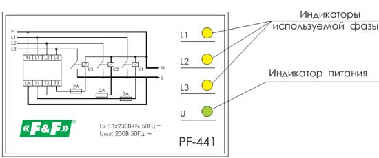
As a rule, automatic phase switches must be used in conjunction with contactors, because. the rated current of the switch contacts is only 16A. For some loads, it may be enough.
PF-441 has priority phase L1. If the voltage on phase L1 goes beyond (190-250)V, then the phase switch switches the load from phase L1 to phase L2 or to phase L3. When the voltage is restored on phase L1, it switches the load back.
But, there are phase switches that can be used without contactors: PF-40A, PF-60A, PF-80A.

The device is operational (capable of switching the load) if there is at least one phase at the input, provided that its voltage is not lower than 200 Volts (for PF-40A), or 180 Volts (for PF-60A and PF-80A).
Manual phase switches.
When looking for a manual phase switch, you need to pay attention to the required rated current. In my case, I needed a 63A switch.
The only manual phase switch for 63A that I could find is a 4G type cam switch. Moreover, it is not called as a phase switch.
Diagram of a manual phase switch - 4G63-108:

From this manufacturer, you can pick up switches with the desired switching scheme from 10 to 100A. I did not find other analogues. Up to 40A something else can be found.
By the way, it can be used as a manual phase switch. Requires 2 switches 1P:

If you know other phase switches, add them in the comments.