Submersible pump control circuit
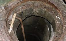
The presence of running and drinking water is the most important component of comfortable living and recreation outside the city. In a situation where central water supply is not available, the only right decision is to drill a well or well and then install an automatic submersible pump. The uninterrupted operation of the unit depends on the control system, which is assembled according to different schemes.
Submersible pump control - the feasibility of automation
To equip a country house with a fully functional water supply system, it is necessary to automate the process of filling consumable containers. The pump control must be reliable in operation and simple in design.
Automation of the pumping station allows you to achieve uninterrupted and reliable water supply, reduce operating costs and labor costs, as well as reduce the volume of control tanks.
To organize automatic operation of the pump, in addition to standard general-purpose equipment (magnetic starters, contactors, intermediate relays and switches), special monitoring / control devices are also used. These elements include:
- jet relays;
- level and filling control relay;
- electrode level switches;
- capacitive type sensors;
- various manometers;
- float switch, etc.
Submersible pump control options
There are three types of devices for controlling a submersible pump:
- control unit in the form of a remote control;
- press control;
- automatic control with a mechanism for maintaining a constant water pressure in the system.
The first option is the simplest control unit that can protect the pump from power surges and possible short circuits. Automatic operation is achieved by connecting the control unit to a level or pressure switch. Sometimes the control panel is connected to a float switch. For a similar automation unit, the price does not exceed 4000-5000 rubles. However, it is not expedient to use such a control without protecting the pump from dry running and the pressure switch.
There are blocks with built-in systems, for example, "Aquarius 4000" worth 4000-10000 rubles. A significant plus of the equipment is ease of installation. Installation can be done independently without the involvement of specialists.
The second option - "press control" is equipped with built-in systems of passive protection against dry running and automated operation of the pump. Management is based on focusing on a number of parameters, among which the level of flow and water pressure is necessarily taken into account. For example, if the water flow is higher than 50 l/min, then the equipment under press control adjustment operates continuously. As the water flow decreases / pressure increases, the automation is activated and the press control turns off the pump.
When the liquid consumption is less than 50 l / min, the pump starts with a decrease in pressure in the water supply system to 1.5 atmospheres. This function is especially important in conditions of a sharp jump in pressure, when it is necessary to reduce the number of on / off devices with a minimum flow of water.

Successful models of press control equipment: Brio-2000M and Aquarius.
The third option is block control with maintaining a stable pressure throughout the system. It is advisable to install this device where pressure "jumps" are highly undesirable.
Important! Stably high pressure indicators increase energy consumption, while the efficiency of pumping equipment decreases
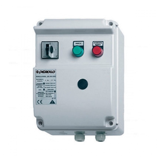
Submersible pump control cabinet: necessity and functions
The control cabinet is an indispensable element of an autonomous water supply system operating on the basis of a submersible pump. It integrates all control, control units and safety blocks.

With the help of a switch cabinet, it will be possible to solve a number of problems:
- Ensuring smooth, safe start-up of the pump motor.
- Regulation of the frequency converter.
- Tracking the operational parameters of autonomous water supply: water temperature, pressure in pipes, level in the well.
- Alignment of the characteristics of the current that is supplied to the terminals of the electric motor and regulates the speed of the pump shaft.
The control cabinet serving several units at the same time has extended functionality:
- Control of the frequency of operation of the pumps. Control units alternately ensure uniform wear of the machine part of the equipment. This almost doubles the service life of pressure equipment.
- Monitoring the continuity of the units. If one pump fails, the well will continue pumping water on the second (reserve) line.
- Monitoring the functionality of pumping equipment. During the downtime of the device, its silting is prevented.
Standard equipment of the control cabinet
The distribution cabinet for a submersible pump (water, drainage, fire) consists of the following elements:

- Case - a metal box, designed for the installation of electrical equipment.
- The front panel is made on the basis of the housing cover, in which the "Stop" / "Start" buttons are built. On the front side, indicators of the operation of sensors and pumps, as well as a relay for switching from manual to automatic mode, are mounted.
- The phase control unit consists of three sensors that monitor the load by phases. The device is installed near the “entrance” to the control cabinet hardware.
- Contractor - a switch that supplies electricity to the terminals of the pumping unit and disconnects the unit from the network.
- A fuse is a special relay that eliminates the consequences of a short circuit in the system. In the event of a short circuit, the fuse element will blow, not the motor winding or the contents of the cabinet.
- Control unit - controls the mode of operation of the unit. It consists of a pump off / on sensor and an overflow sensor. Sensor terminals are inserted into the hydraulic tank and into the well.
- The frequency converter controls the shaft speed of the asynchronous motor, resetting and increasing the speed at the moment the pump is turned off and started.
- Pressure and temperature sensors are connected to the contractor and block the start of the unit in improper operating conditions - icing of pipes, pressure increase, etc.
Such a "stuffing" of control cabinets is taken as a basis by many manufacturers. But at the same time, some companies introduce innovative solutions into the standard scheme, increasing the competitiveness of the product.
Overview of control units from different manufacturers
Automatic station "Cascade"
The Cascade submersible pump control station is designed for automatic control/protection of the unit's three-phase electric motor, rated at 380 V. The station is a metal cabinet with a lock. The kit includes:
- control station;
- dry running sensor (conductometric type);
- level sensor;
- passport and instruction manual.
Technical and operational characteristics of the station "Kaskad":
- rated current - up to 250 A;
- working position - vertical;
- supply of level sensors with alternating current;
- current measurement by load phases;
- supply voltage - 380 V;
- degree of protection - IP21, IP54.
Emergency shutdown in case of:
- overloads during operation and at the time of launch;
- breakage of one / two phases;
- "idling" of the engine;
- overheating of the electric motor;
- low well debit;
- short circuit in the motor circuit.
Control device "Height"
The Vysota submersible pump protection/control device is designed for centrifugal downhole units with a capacity of 2.8-90 kW. Main functions:
- pump start/stop depending on the liquid level in the tank;
- shutdown of the unit in case of short circuits;
- dry running protection;
- motor insulation resistance control;
- phase load control.
Important! If the level sensor is not used, then the device can be operated in remote control mode
The principle of operation of the station "Vysota"
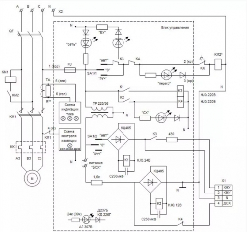
If there is no water in the tank, the lower and upper electronic sensors (KNU, KVU) are open, and relay K1 is de-energized - the pumping equipment starts. At the upper liquid level, the KVU contact closes the circuit, the K1 relay is activated and opens the starter coil circuit - the pump is turned off. After the water level drops below the KNU, the electric pump is switched on again.
Short circuit protection of the electrical circuit is provided by the QF switch, control circuit by the FU fuse. The current thermal relay KK protects against overloads; when triggered, the light with the inscription "Overload" lights up.
Control device Aries SAU-M2
The device for controlling the submersible pump Aries SAU-M2 is used to maintain the water level in storage tanks, reservoirs, settling tanks and drainage complexes.
Specifications and operating conditions:
- nominal voltage - 220V;
- permissible deviations from the recommended voltage level - +10 ... -15%;
- maximum allowable current - 8 A;
- liquid resistance at which the sensor is triggered - up to 500 kOhm;
- case protection degree - IP44;
- ambient temperature - +1…+50°С;
- relative air humidity - maximum 80% at +35°C;
- atmospheric pressure - about 86-106.7 kPa.
Functional diagram of the SAU-M2 submersible pump control unit
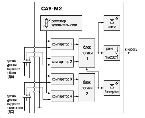
When the water level in the tank reaches the bottom mark, where the long tank sensor electrode is installed, the tank is automatically filled to the upper level, where the tank sensor short electrode is mounted. 2 three-electrode sensors are connected to the device:
- filled tank level sensor;
- level sensor in the tank used for fluid intake (well).
Comparators 1-4 compare the signal values with the reference value, after which they issue a signal to turn on / off the pump relay, to which the unit's electric drive is connected.
The "Pump" relay turns off when the short electrode of the capacity sensor is flooded and turns on when the long electrode is drained (lower level).
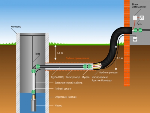
A simple submersible pump control circuit
For the arrangement of country water supply on a small elevation, it is desirable to place a container for accumulating water. From the tank through water pipes, water will be supplied to the house and the necessary places in the garden. The figure shows a diagram of the simplest pump control mechanism, which can be organized independently.
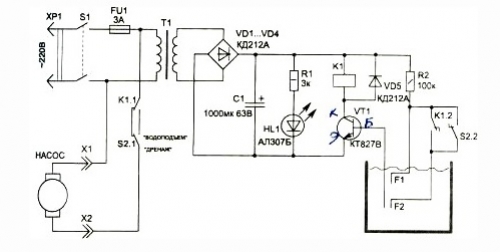
The circuit consists of a small number of elements. The advantages of such control are ease of installation and reliability.
Principle of operation:
- Starting and switching off of the unit is carried out by the normally closed contact of relay K1.1.
- The operating mode is selected by switch S2 (water lift-drainage).
- Sensors F1 and F2 monitor the water level in the tank (an ordinary wooden barrel or a plastic container can be used as a tank).
- Switching on the power supply with switch S1, in the case when the liquid level is below sensor F1, the relay coil is de-energized - the pump starts through the closed contacts of relay K1.1. After the water rises to the sensor F1, the transistor VT1 opens and turns on the relay K1. The normally closed contacts K1.1 will open and the unit will stop.
The control system uses a low power transformer from the broadcast receiver. At the same time, it is important to observe that the voltage across the capacitor C1 is at least 24 V. The KD212A diodes can be replaced by any diode with a rectified current of the order of 1 A and a reverse voltage of more than 100 V.